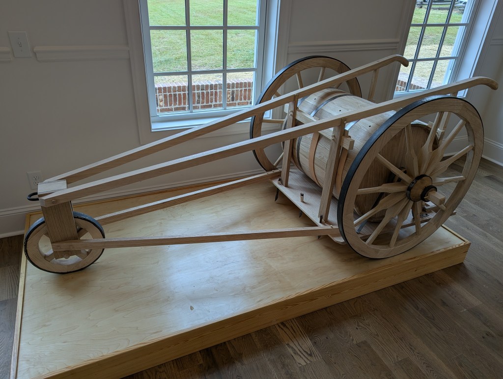
Full-size Seed Plow

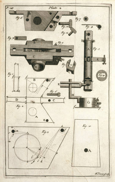
In 1701 an Oxford educated farmer refined the “seed drill” which had been in use for centuries. His name was Jethro Tull and his design used a complicated wheel-driven mechanism to drop a seed at a specific interval in a row. It was a delicate, intricate machine and required a furniture maker’s skill to produce. Here are a couple of drawings he used for patent purposes.

George Washington learned of the existence of Tull’s machine in the middle of the 18th century and ordered one, perhaps understanding the benefit of placing seeds as opposed to sowing seeds. He absolutely understood that if the colonies were to survive, nearly everyone needed to grow food. He likely surmised that the simplest way to accomplish this goal involved a simplified version of a seed plow. He took Tull’s ideas and created a seed plow that did not require a furniture maker and was not as susceptible to breakage as Tull’s model. Washington had his slaves make his seed plow. He did not patent it so that it would be available to everyone free of charge. Unfortunately for historians, this means that no drawings were made to keep on record at the patent office. No drawings are known to exist.
Because there are no existent measured drawings or plans of Washington’s design, this is my interpretation of the machine. There are a few hints in existing letters from Washington. For instance, the plow is known to have a cask because he states the cask can be six feet wide if desired. It is also known that there were holes in the cask at the desired intervals for seeds to be deposited. Leather straps were known to be used to keep the seed from falling before or after the desired spot. We know this because he states that copper could be shaped to cover the leather to keep the leather from wearing out prematurely.
In 1791 on his tour of the southern states, Washington met John Chesnut who was a landowner and farmer in Camden, SC. Washington sent Chesnut a seed plow shortly after their meeting. My property borders the estate that John Chesnut once owned. I am told that Washington’s seed plow survived into the mid-twentieth century. It was not recognizable as anything but a pile of sticks because it was burned in a barn clean out. Chesnut’s descendants still have the 4-page letter that Washington wrote and in it are a couple of hints as to its design. As my interpretation of this seed plow progressed, I continually asked “What would be the simplest solution?” Washington wanted anyone to be able to build one. This is the only interpretation of Washington’s seed plow known to exist.
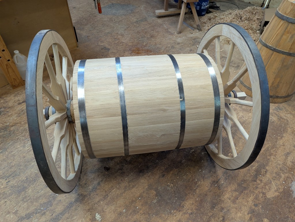
I began with wheels. The whole machine is neither large nor that heavy so the wheels could be lighter in design than canon or wagon wheels. The seed plow wheels do not rotate independently but are directly connected to each other. As the wheels rotate the cask also rotates. The simplest way to accomplish this was to connect them by running a square axle through the hubs and through the cask. This square axle provides the rotation of the cask in perfect sync with the rotation of the wheels as they travel across the ground. Also, because the wheels do not rotate independently, turning around at the end of a field, one has to pick up the wheels (and attached cask) and rotate 180° using the smaller front wheel as a pivot.
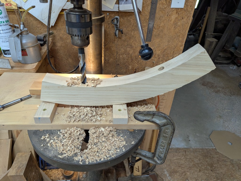
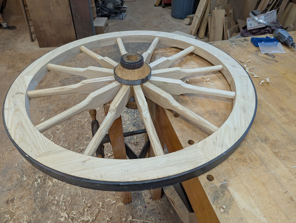
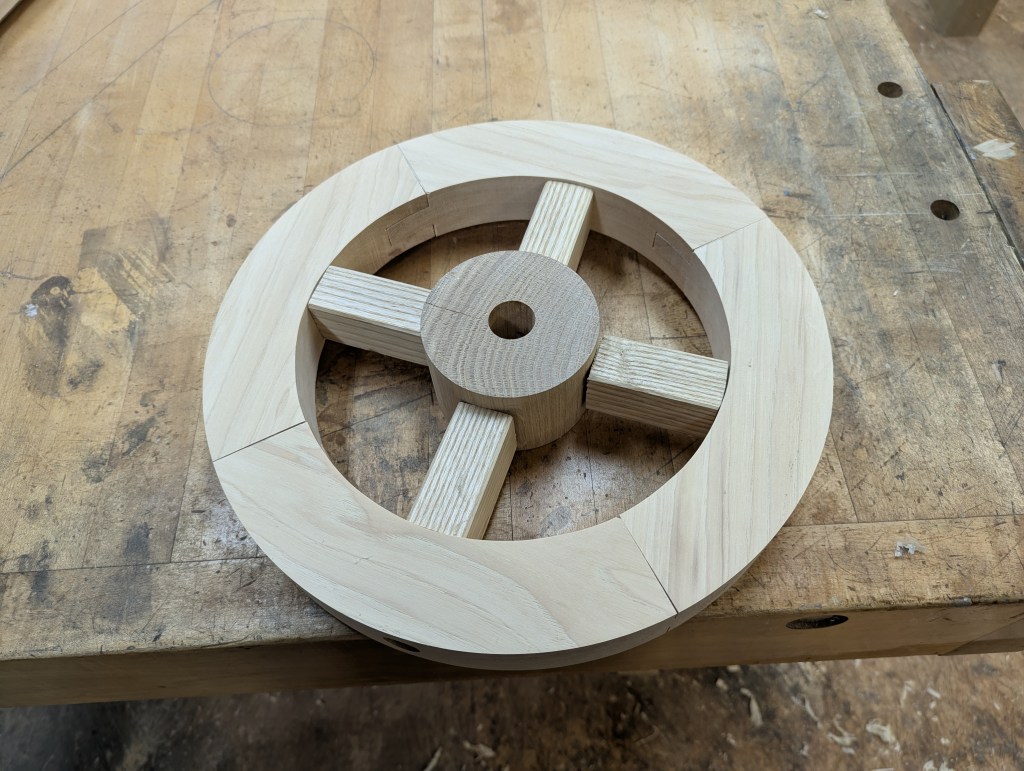
The wheel hub is made of oak turned on a lathe using a form common to the time with one exception. I made a slight depression toward the outer edge of each that is ¾” wide. This is to corral a metal strap necessary to the structure. It will be clear later in the build.
I heated, placed and rapidly cooled three steel bands to insure the hub would not split apart. I then cut the axle made of hickory to size and length so it could be used to gauge the opening through the hub. It needed to be snug but not tight. I laid out mortises for the spokes and then chiseled them out.
The spokes are ash. I rough cut the shape on the band saw and cut the tenon on the table saw. My shave horse was put into service to shape the round part of the spoke using my grandfather’s draw knife and an old wooden spoke shave. There are two spokes per fellow and six fellows per wheel so I needed 24 spokes.
I then drove the spokes into the hubs held in place on my wheel stand. The wheel stand is a period-correct piece I saw drawn in a historical reference book and thought it was absolutely ideal for what I was trying to do. Once the spokes were set I measured out from the hub for both the shoulder and the full length of the tenon. I cut each spoke round at the end away from the hub. The round cut is smaller than the total diameter of the spoke shaft. It looks like a dowel sticks out the end. This is a tenon that is the same size as a hole drilled into the fellow. The shoulder stops the fellow from sliding too far up the spoke shaft.
The fellows are ash and after roughing out the shape I sanded them to the line and carefully cut each end at 60°. I measured and marked for holes and then drilled into the fellows to create the mortises for the spokes to slide into.
Next I drove the fellows onto the spokes and fine-tuned them.
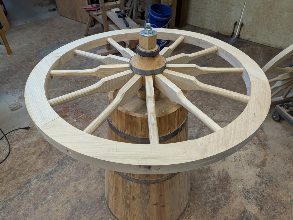
Once the fellows were in place and adjusted, I carefully measured the distance around the outside using a traveler. I bent steel flat stock in a circle and used the traveler to transfer the measurement of the wheel’s circumference. In order to get a tight fit that holds all the wheel parts together, I shortened the length of the steel by .3%. Then I cut the steel and welded the ends together to this slightly smaller circumference making a ring.
The next step was to heat the steel and we (The Historic Camden Woodworkers Guild) built a simple fire using hardwood. Steel expands at a rate of 1/8” per foot at 900°. Once it was hot, the circumference was large enough to fit over the outside of the wheel. We placed the steel level with the wheel and immediately began to quench it with water. When it shrinks it tightens up all the joints between the fellows, between the fellows and the spokes and between the spokes and the hub. The end result is a wheel so tight it bounces. I actually held the wheel up over the concrete walkway and dropped it. It bounced up!
Now that I had a pair of wheels and a square shaft to connect them, I began work on the cask. I determined the three rows of seeds would be ideal with 11 inches between the rows. I also calculated into the mix the distance from the outer holes to the wheels so that if the farmer followed the outer wheel track in the opposite direction, the holes closest to the wheel would be 11 inches from what was deposited when he went in the opposite direction. The wheel track would then keep the distance between rows consistent.
The cask I made was 30 staves, 6° each with very little taper to help with the seed distribution. Some taper is necessary in order for the hoops to tighten as they are driven on. If the cask were straight, the hoops would slide from one end to the other without tightening. But too much taper and the seed would be concentrated in the center where it would be deepest and the outer holes, then, would not be dropping seeds.
I then “stood up” the cask and measured for hoops. I cut and riveted the hoop ends together and drove them on the cask with a “hoop driver.”
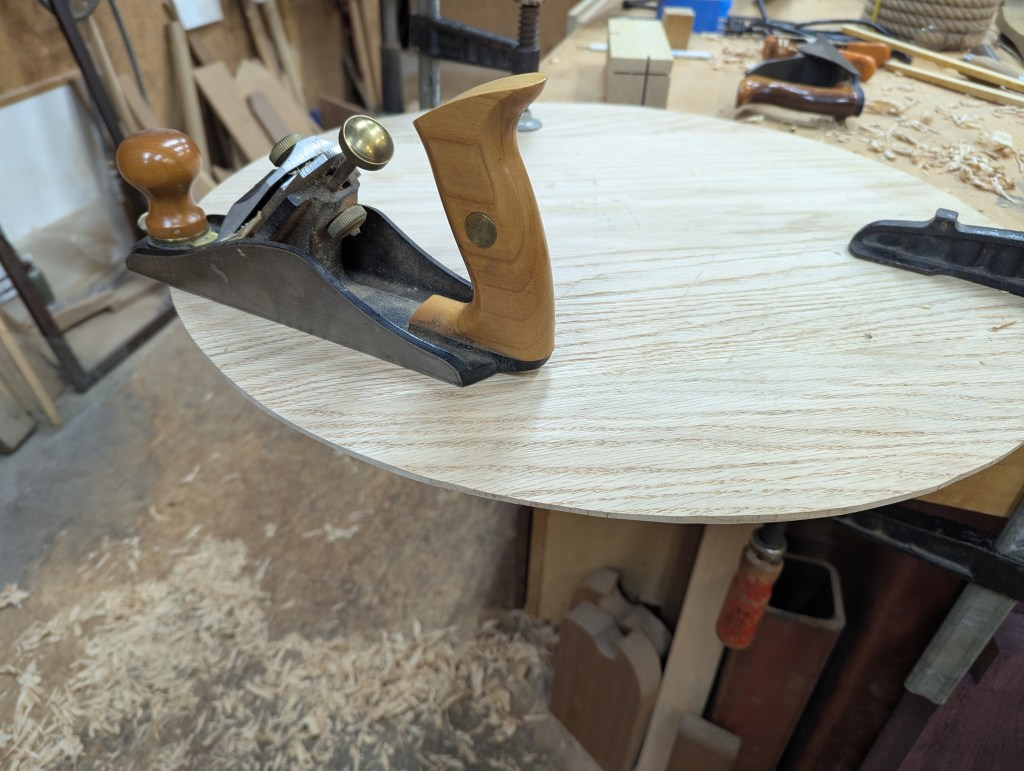
Next I used a “croze” to cut the appropriate size groove in the wall of the cask at each end to accept the head. The head’s exact size is determined with dividers. The dividers are started at a known point (for instance a marked joint between two staves) and “walked” end for end around the cask in the groove. When six turns of the dividers ends at the same spot as it began, that distance on the dividers is the radius of the head. Those same dividers are used to score the piece of wood to be used for a head.
I cut the heads to size, and tapered the edge to insure a snug fit in the groove. Once the heads were cut and tapered, I cut a square hole the size of the axle dead center in each. The first head could be secured in place without worry of the direction of the square center. The second head, however, had to be lined up using the axel before it was secured in place. The holes could not be twisted to line up once the head was in place.
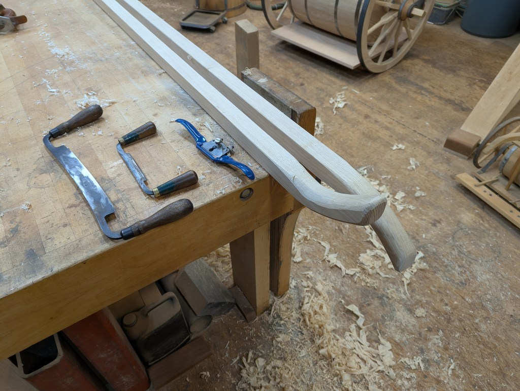
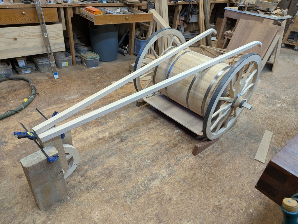
The wheels and cask were now assembled and rolling as a single unit. In order to have a modicum of control over the direction the unit would take, there needed to be handles in the back for the farmer to hold and that would converge to a single point in front. This same point would double as a convenient place to attach the means to pull the seed plow.
At this same point I also made and installed a small wheel in the front where the two handles met for two purposes. One was to create a triangle horizontally to keep the cask, plows and harrow fairly level. That is, if the machine tilted back the plows would not cut their groove at the proper depth and the harrow would dig too deep. And vice-versa if it tilted forward the plows would cut deeper than intended and the harrow would not do its job. It is of course all relative because no field is as flat as a pool table. But three points of contact do help.
The second purpose is to have a pivot point for turning the plow around. Because the wheels are not turning independently they will not easily go around a corner, so when turning around at the end of a row in a field, a pivot point enabling the farmer to pick up the cask end and walk it 180° without turning out more seeds by rotating the wheels.
The next challenge was attaching the handles and front wheel to the large wheels and cask. The axel is square so it is inappropriate for bearing. One could make a round bearing with a square cut out center that would fit on the axel (which I did on the model). But in an effort to keep the build as simple as I could, I extended the hub on the inside when I was turning it and added a grove. This groove is between the edge of the wheel and the edge of the cask. This is the bearing from which the bottom plate hangs on steel straps. The plate attaches just below the cask and just above the ground.
I used steel straps to ride on the bearing point as it would have been available (even if it was more iron than steel), but this connection could have just as well been made of wood. Neither the weight of the connection nor the slow speed at which the woods rubbed against each other would have caused much heat or wear.
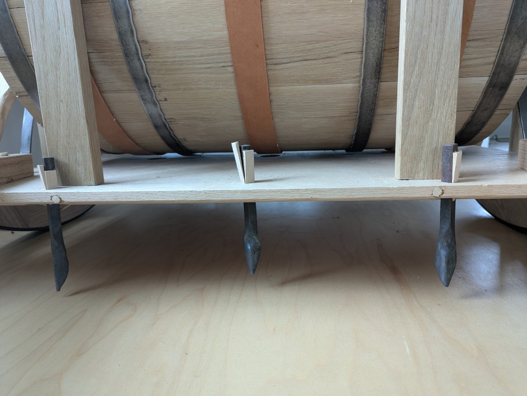
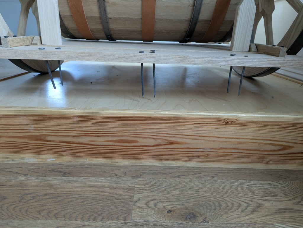
Vertically from the plate are four posts, two on the front side of the cask and two on the back side. These posts are connected to handles directly. Horizontally there are connecting boards up near the handles. These horizontal boards have two purposes. One is to further stabilize the handles and the second is to hold the leather straps that are slung under the cask.

I arranged these straps in line with the holes around the cask. I drilled the holes in the cask at measured intervals to allow the seed fall at those intervals. In order to keep the seed from falling out of the hole prematurely, the leather straps keet the seed in the cask both on the way down and on the way up as the cask rotated. At the very bottom the straps have a hole in them to allow seed to fall through. There is a corresponding hole in the bottom plate.
I attached small plows to the bottom plate as these are needed to open the earth so that the seed was deposited below the surface of the ground thereby having a better chance of not being eaten by animals. The plows are small. The seeds do not need to be planted deep. At the back side of the bottom plate I attached a harrow that would cover the seed with a little soil. The harrow is hinged so that the grass that gets tangled up in the tines could be easily cleared.
So, with a bit of head scratching and reasoning to find the simplest solution, this is my construction of what is known as George Washington’s seed plow. This seed plow really was a genius and well-timed invention as it’s construction was simple enough for most farmers to reproduce and it was a much more economical use of seed than broadcasting by sowing. The seed had a much better chance of germinating and therefore of generating a crop for the growing population.
Wonderful history story and completed replication. Thanks for sharing the journey and background