Building the Cannon Carriage
My last post detailed the building of the Cannon Wheels. Those wheels were affixed to a rather stout set of rails and cross members that comprise the carriage. I thought these components were a bit over the top size-wise until I saw a smaller cannon discharge. The amount of energy released was astounding! I reevaluated the amount of mass that was being used to control the recoil of the cannon and concluded that it was actually on the short/light side. At the time of the Revolutionary War, these carriages were probably a compromise between mass and portability.
The book I was given as a resource was the British Manual on building various size cannon and other carriages published in 1752. It had general measurements for various size cannons from 3 pounders to 12 pounders. Historic Camden had been gifted a 6 pound French Cannon reproduction. The table of measurements had overall length, thickness and width of stock needed. None of the tables had details such as measurements for where the downward slope of the back end began, or how high the trail was as it began its curve. “Guesstimating” became a close friend.
The “Cheeks” are the two side pieces and the longest parts. The manual listed these as beginning with boards 11 feet long, 16 inches wide and 3 1/2 inches thick. The wood of choice for cannon cheeks was White Oak in that it is an extremely tough wood and very weather resistant. The White Oak available to me was at best half the thickness needed. Fortunately, the director of Historic Camden knew some hardwood lumber industry people in Kentucky and he was able to locate a sawmill that cut 4 inch white oak as a regular product. The problem was shipping. However, if I could pick the wood up they would have it ready within a week. It would be “green” that is, not kiln or air dried. They said each board weighed about 600 pounds.
My friend who loves road trips was on-board to drive a U-Haul to Kentucky. It was a 6 hour drive to get there. We were there shortly after noon and the mill had us loaded and on our way by 1:30. Including the additional 2 inch stock I suggested we get as long as we were making the trip, we had about 3 tons of White Oak.

I was able to unload the truck with the help of my good friend Archimedes. He was also instrumental in helping me move these monsters around my shop. I cut 4 feet off the length of the big boards which dropped 150 pounds, but I still had a pair of 450 pound boards to send through my thickness planner. This is a little more weight than I can handle.
Rolling adjustable height tables were the solution. With the Oak on the infeed side of the planner, the first rolling table held up the far end.

The second table waited at the outfeed side of the planner and as it cleared I gently adjusted the rolling table upward to take the weight and it moved away from the planner with the end of the oak nicely supported.

A floor crane I made a few years back carried the plank from the outfeed side to the infeed side for the next pass.

The drawing in the book had no dimensions on it because it was used for all the sizes of cannons. I used some copies of these drawings and adjusted the size to create a copy 11 inches long, since the carriage I was to make was 11 feet long. I drew parallel lines along the length and then divided the space into 11 equal parts. Using ¼ inch plywood to mock up the 11 foot long cheek blank I drew lines making 10 divisions. Then, by my one good eye, transferred the shape from 11 inches to 11 feet and cut the plywood with a jigsaw.
After tracing the plywood pattern on the Oak, I used the hand-held band saw to cut out the final shape – or what I thought was the final shape.

Historic Camden did not at this time have in its possession the cannon barrel itself, so we had no way to check for appropriate size.
Cutting the four transoms was next. There is one at each end and two in the middle all of which are mortised into the cheeks and through bolted. They are all at different angles to the top and bottom of the cheeks and also angled from front to back. The cheeks are spread farther apart at the “trail” or back end than at the front end.

Once the tenons were cut on the transoms I could trace them on the cheeks and cut the mortises. I checked multiple times to insure I was not cutting mortises on the right-hand side of both cheeks.
Using my drill press and long bits I drilled the transoms all the way through. Placing them in the mortises I used the newly drilled holes as a guide to drill through one cheek. With all the holes drilled on one cheek, I assembled all the pieces and drilled the second cheek from the holes in the first cheek through the transoms.
After bolting everything together the cannon carriage weighed somewhere in excess of 600 pounds. I needed to bring it to Historic Camden so that the blacksmiths could begin their work. And of course, we were under a time crunch.

We settled the carriage on ponies outside the blacksmith shop and days later the cannon barrel arrived. It was smaller than we expected. Even though it was copied from a six-pounder, it looked lost on the 11 foot carriage.
We concluded that about 18 inches needed to be removed from the cheeks. Once I had done that (and made a new front transom), it looked much more in proportion. The blacksmiths could now begin to fabricate the many attachments and secure them in place.
As the blacksmiths worked on the fittings, I was then able to finish the wheels and axel. The axel was quite a challenge all to itself. The center is rectangular and from that rectangle tapered cones are cut on the ends. And these tapered cones are angled down.

The first step was to rough out the taper with my hand-held band saw. I then marked location for the various diameters – 3 ½, 4, 4 ½, and 5.

Then using a draw knife and a spoke shave, I made the square corners round. I was a process of checking with the hole pattern, seeing where material needed to be removed, and then removing some more. And repeat.


The temptation is to remove a lot of material and be done, but there is no putting it back once it has been removed. So I had to sneak up on the perfect size by a bit of shaving here and a little shaving on the opposite side.
Once it appeared to be close, I applied a liberal amount of graphite to the inside of the hub, placed the hub on the axel and spun the hub.

Where the graphite stuck to the axel was where more material needed to be removed. This I repeated until the hub was rubbing the rectangular section of the axel. The inset metal strip on the bottom side was to reduce wear on the axel.

Once the wheels were finished and mounted on the axel and tested to ensure they did in fact roll properly (and didn’t seize or squeak), they were mounted to the cheeks.
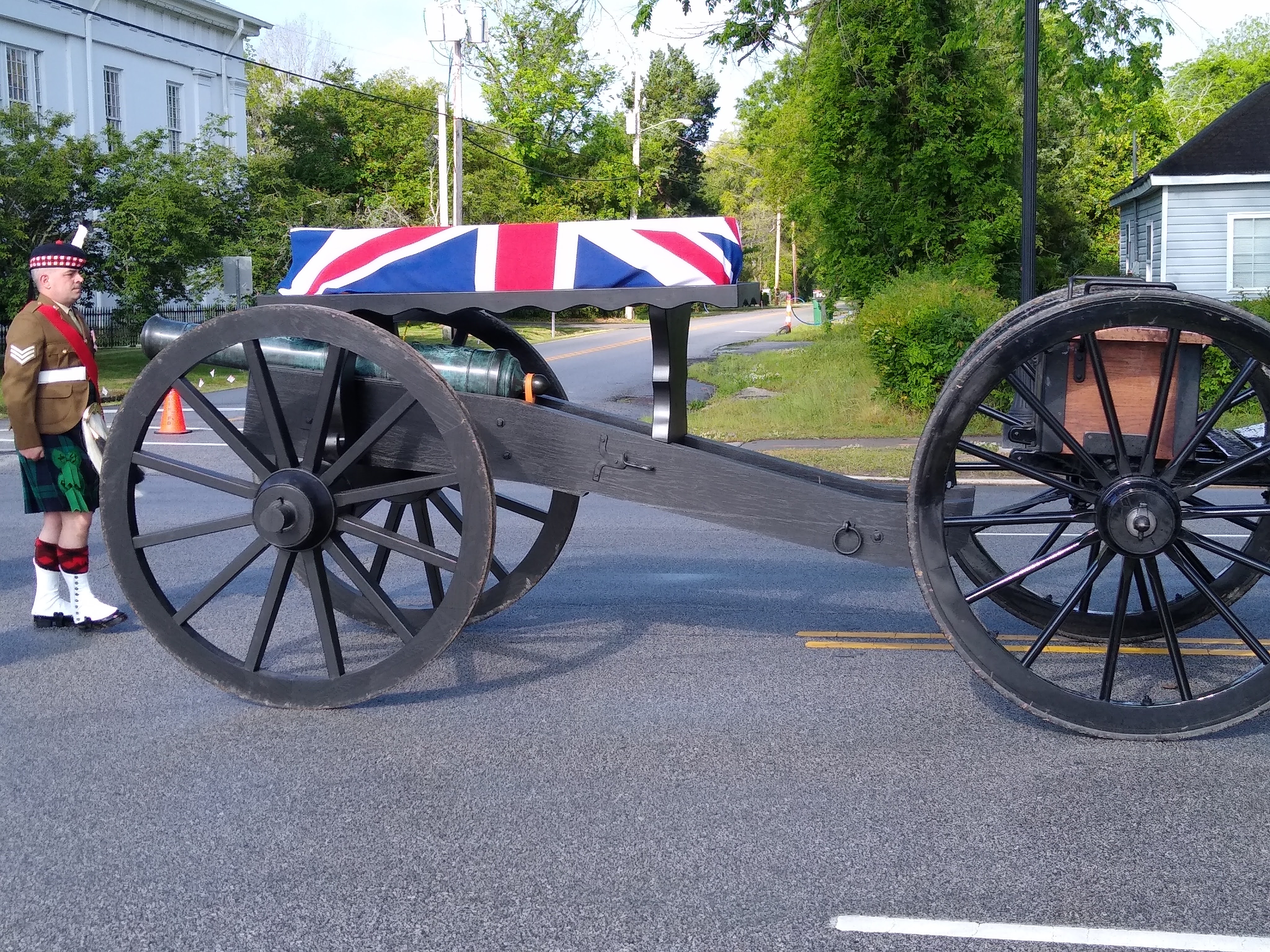
A very few hours after the wheels were installed, the cannon was taken to the Steeplechase Museum where it was on display for the evening’s festivities preceding the annual races the following day (April 1 this year). The build was not yet complete, however, as the reason for the cannon carriage in the first place was to carry a Scottish Highlander’s remains at the ceremonies April 22.

The ceremonies were in honor of 14 Revolutionary War soldiers whose remains were discovered and carefully removed from the site of the Battle of Camden. Of these 14, twelve were Continental Soldiers, one was a North Carolina loyalist and one was a Frasier Highlander. It is the common practice here in the US to place a coffin (or casket) on a caisson in a military funeral procession. A caisson is a two wheeled transport of ammunition held in boxes. The practice in Britain is to place the coffin on top of a cannon as the world witnessed in the recent ceremonies honoring the late Queen Elizabeth.
Historic Camden’s executive Director felt it would be appropriate to honor this Highlander in the British fashion.
There are no specs on the size, shape, or location of supports or platform for an 18th century cannon to be used in a funeral procession. And two sticks crossed making an “X” with a board on top just seemed so woefully inadequate. Gentle curves, like those of a Grecian urn, however, seemed to be the answer. The curves positively distinguished the coffin platform from the hard lines of the cannon carriage.
The platform was not to exceed 50 inches above the ground. The front support rests on the axel and it needed to clear the cannon barrel precisely where the handles are located.

That did not leave much material for stability. My concern was that the platform (and coffin) remain rigid and fixed to the cannon even with an unexpected jolt from a spooked horse. The support toward the trail end needed to be much taller due to the drop of the cheeks of the cannon carriage. This support extends down between the cheeks and is secured with screws. This one remains solid with an area large enough to place a copy of the Highlander’s Standard (Banner).

The platform itself is 2 layers of ¾” plywood glued together and finished with a scalloped edge. The plywood is down 1” from the top of this trim creating a “tray” so the coffin would not slide off unintentionally.
It was an honor be the one make this cannon carriage, to see the cannon in ceremonial engagement and to watch the “Scots” honor their ancestor.

So fun and interesting to follow along on the journey to the incredible beautiful finished work. Your attention to the finest of detail shows up well in the photos!
Beautiful work of art and document. Enjoyed both very much. I have built several scale cannons from the Civil War era (three of my Great Grandfathers fought in the war). Three of my earlier Grandfathers fought in the Revolutionary war also.
I would be honored to make a scale model of either a three pound or six pound gun in honor of their service also and would appreciate any information you might have or where additional information might be found.
Thank you again for your post.
Best regards.
Douglas Kysar
Doug kysar1@gmail.com
Douglas-
Thank you for your kind words.
I used a British manual printed in 1780 entitled A Treatise of Artillery by John Muller.
Cheers-
Philip