Half-Scale Model of Water-Powered Tilt Hammer

A couple of years ago I designed a new Blacksmith Shop for Historic Camden. I worked with the Blacksmiths to create a space that would resolve some of the shortcomings of the present space. We are actively working on building that shop now. The new shop will include a unique feature, a water-powered tilt (or trip) hammer. I understand that when it is up and running it will be the only one operating in the country.
Blacksmiths have historically used the tilt hammer to form and shape large pieces of hot iron instead of having multiple men swinging sledge hammers to do the work.
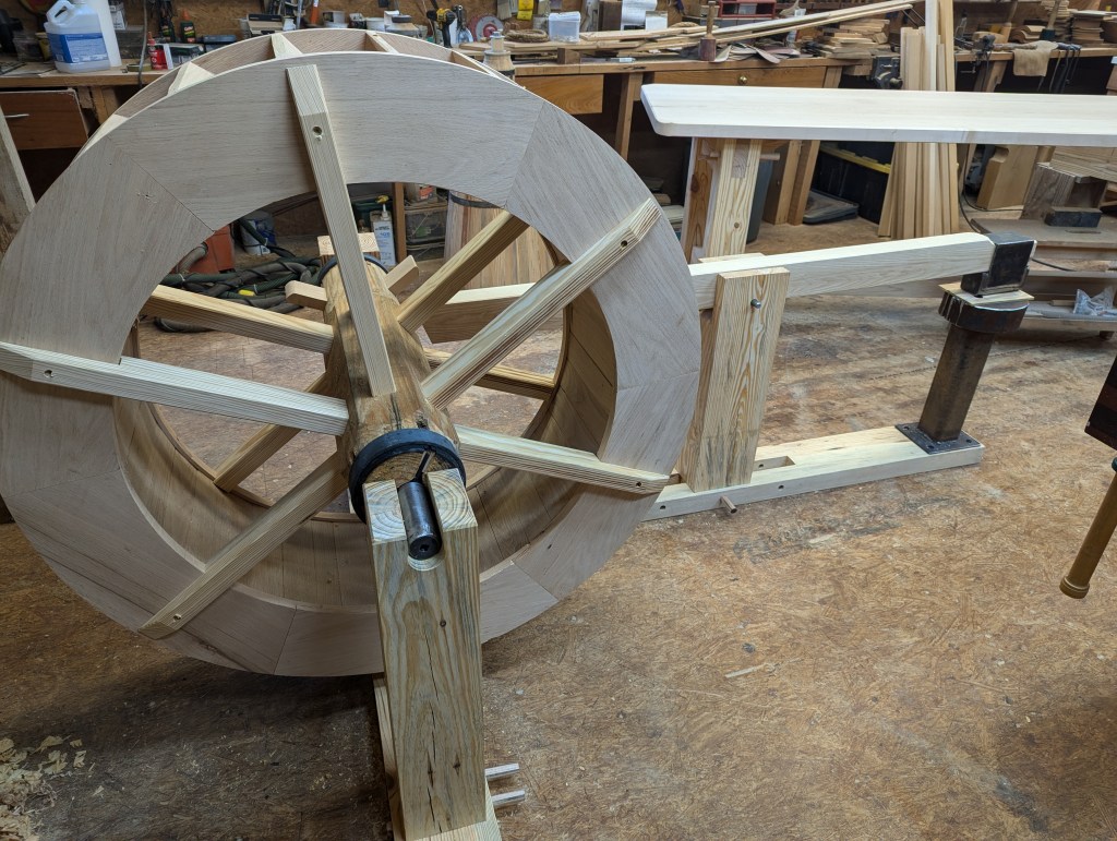
Here is a photo of the half-scale model I completed of the water-powered tilt hammer. Water filling the buckets of the water wheel cause it to turn (counter-clockwise in this image).

The paddles on the shaft just this side of the water wheel push the wooden beam down.

As the paddles clear, the heavy end farthest from the water wheel shaft drops and moves the metal just like a hammer blow.
This is a view from the end.
I had never made a water wheel before although I am very familiar with the four components. Constructing the wheel in a manner consistant with the known technology of the 18th century was a challenge. How does one hold all these pieces together and keep them together when under the pressure of water weight and torque of levered resistance? The use of nuts and bolts or screws would be the answer today. But these were rare in the 18th century countryside. Even the humble nail was precious.
I began by forming the rims. Each rim is made of 4 pieces that have an overlap joint that is pegged with wooden pins. After determining an appropriate angle for the bucket boards to capture water, I made a jig for my router to follow. I evenly divided the circle and routed negative dovetails. Using dovetails was an idea I thought worth a try. I have not seen this done in any water wheels drawing or documentation. But it was a common wood connection practice at the time. Next I cut a groove just inside the bottom edge of the two rims. This groove would capture the soal boards much the same as a bucket bottom is captured by the groovesides. I then mirrored this pattern on the opposite rim.
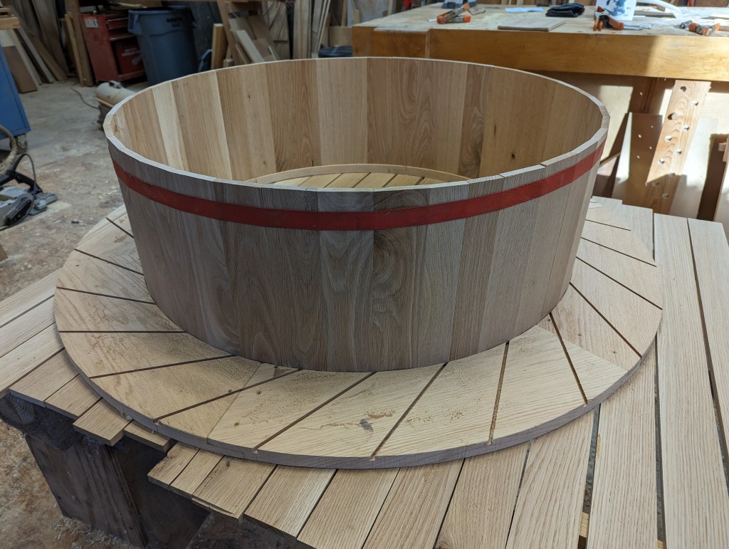
The bucket boards were next. After cutting width length and thickness, I cut positive dovetails on each edge. Once I slid all the bucket boards into place the wheel became remarkably rigid. It worked! No nails, no screws, and no bolts, and the wheel not only held together but became rigid.
Next I created a six-sided shaft about four and a half feet long. I cut mortises into each of the six sides for the spokes that connect the water wheel to the shaft. There are six per side so twelve mortises. The gudgeons and wedges are also visible in this photo at both ends of the shaft.
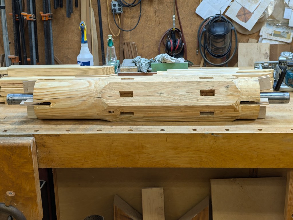
I fabricated two gudgeons. The gudgeons have “wings” that are set into slots cut in the ends and then, with the use of wedges, adjusted straight and centered on the shaft. The gudgeons are a necessary component of any water wheel operation without which the weight of the wheel and the water would very quickly wear down the wood where it contacts the support at the ends. (The spokes are visible in the background).
Once the gudgeons were placed and wedged, steel bands were measured slightly undersized to fit over the ends. These bands were then heated to expand them. The blacksmith at Historic Camden, Rick Thompson, helped me with this operation. It is tricky in that the steel is way to hot to grab with anything but tongs, and after it is placed over the end it needs to be hammered down all while it is creating a cloud of smoke making it hard to see. And finally it gets doused with water which causes the ring to shrink and hold very, very tightly.
Once I had the shaft completed, it was time to add the wheel. At this point I learned a valuable and in hindsight, obvious lesson. It is one of the reasons I make models. As I make them I become aware of order, distance, function, clearance and other things. All may work perfectly in my mind or on paper but reality is another matter (pun) altogether.
I had cut my spokes with a little “thumb” that would grab the inside of the rim just touching the soal boards. But I could only use three thumbs per side. Once the first three were in place, I could not pull the wheel over or out of shape to get the other three in place. If I put the thumb in place first, the tenon was way too log to begin to fit in the mortise. I then understood why I had seen so many pictures of water wheels being constructed on-sight in-place. It is otherwise impossible to accomplish.
I chose Ash for the helve (the shaft that holds the hammer head) because of its toughness and flexibility, and affixed a makshift hammer head to the end. It seemed a good idea to make the fulcrum adjustable to try out different pressures on the cams. I welded up an anvil out of some scrap.
I was sincerely surprised at how easily the wheel lifted the 25 pound hammer head. It was smooth through the whole process from initial contact to drop.
I set the tilt hammer up next to the blacksmith’s shop at Historic Camden just before the annual meeting of the Philip Simmonds Artisan’s Blacksmith Guild meeting and they loved it! They played with it all day. It is now covered with blacksmith finger smudges.